Power Factor Role in Improving Power Quality
What is the Power Factor?
Efficiency should be taken into account when designing and implementing electrical systems, in addition to safety and dependability. The amount of energy that the electrical system converts into a form suitable for carrying out useful work is one of the indicators of system efficiency. The PF is one of these requirements in the power system. This test determines how much power was applied to the load in order to perform useful work. A system with an improper PF will cost more and experience more power outages. We will learn about the power factor and its significance of it in this article.
Introduction to electric Loads
It is best to have a basic understanding of the different types of electric loads before looking at the power factor concept. Reactive and resistive loads are the two broad categories into which electric loads fall. The term "resistive loads" refers to loads whose solely resistive elements and components.
In the best-case scenario, all the power applied to resistive loads is put to good use. Working power, true power, and real power are all names for this power. Reactive loads are those that produce no usable power despite the system's voltage drop. Capacitive or capacitive loads are reactive loads. In actuality, these kinds of loads do nothing directly and only produce magnetic flux. Reactive power is the name for this energy.
Different types of power factor
The power factor is the ratio of actual power to apparent power in AC electrical systems. The total power in an electrical system is equal to the sum of reactive power and real power, also known as apparent power. Calculating this criterion, which has a value between zero and one, will reveal the system's effectiveness. The PF decreases as apparent power increase relative to actual power. The losses in the circuit rise as a result of lowering this criterion. In other words, the PF is a great way to gauge how effectively the system operates, and the higher the power factor number, the more effectively our electrical system operates.
In contrast to reactive load circuits, which include motors and transformers, complete resistive consumer circuits, such as incandescent lamps, electric heaters, etc., have a PF of one. The power factor can be pre-phase (Lead) or post-phase (Lag), and its value is -1 PF 0 for capacitor circuits and 0 PF 1 for self-conducting circuits, depending on the direction of the angle between current and voltage.
Three different PF in electrical systems is produced by different types of reactive and resistive electronic loads. For a better understanding of the concept of the power factor, it is crucial to be familiar with each of these factors. Real, displacement and apparent PF are three different categories of PF models. We will become completely acquainted with each type of PF in the paragraphs that follow.
Displacement PF
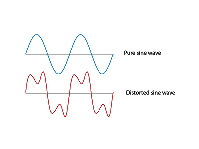
When the voltage and current change phases at the electrical system's main line frequency, a power factor called displacement results. The PF and displacement PF are the same for sinusoidal currents (without distortion). Most industrial customers place a high value on DPF because it is frequently used in utility bills to calculate PF penalties. In most revenue measurement schemes today, only DPF is taken into account.
Distortion Factor
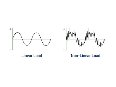
Non-linear devices are widely used in installations today. These devices include things like switching power supplies (SMPS) and variable frequency drives (VFD). Non-linear components also referred to as the Distortion Factor, of the PF are harmonic sources that cause distortions in current and voltage.
True PF
Since there is only the fundamental frequency in the sinusoidal mode, the power factor, or displacement PF, can be calculated as the cosine of the phase angle. PF, however, cannot be characterized as the cosine of the phase angle in the non-sinusoidal case. The true PF, which is the ratio of the total active power for all frequencies to the apparent power supplied by the network, accounts for both the fundamental frequency and harmonics.
The combined effects of a consumer on the sinusoidal waveform of the input voltage are expressed by the true PF, a dimensionless quantity with a range from 0 to 1. It should be noted that the distortion factor and displacement power together make up the real power factor.
True/Total PF = Displacement PF * Distortion PF
This idea illustrates how much of the apparent power the load actually converts into active power. In actuality, the real power factor can be thought of as the total of losses and useful power.
The ability to detect a defective load or reveal a change in the type of load is the primary benefit of measuring the true PF value. For instance, it is possible to identify pump filter clogging by measuring the real power factor. because filter blocking causes an apparent PF to fluctuate over time.
Why is the power factor so important?
After becoming familiar with the concept and different types of power factor, we must admit that calculating and verifying the power factor's amount is crucial. Since there is energy loss in the system if the PF value is low, it indicates that the source energy is not entirely converted into work. This energy loss may result in overload, which could increase costs and even result in a system power outage. Reactive power, on the other hand, increases as the power factor decreases. The main cause of the rise in consumer electricity costs is also more reactive power.
Calculation and correction of power factor
On the presumption that system loads have linear characteristics and that harmonic distortion can be disregarded, traditional concepts for PF correction selection are based. On the basis of this supposition, the PF and displacement power factor are equal. The traditional power factor triangle method is used to calculate DPF, which is represented as follows.
where the fundamental frequency units kW and kVA are used.
The power factor is calculated differently due to harmonic distortion in voltage and current brought on by non-linear loads on the system. The ratio of true power to the circuit's total volt-amperes is known as the true power factor (TPF):
Even though the definition of power factor is the same for kW to kVA in this instance, kVA also includes harmonic distortion volt-amperes. Multiplying the true rms voltage by the true rms current yields the total kVA (apparent power). With distortion, active power typically only slightly rises.
If harmonics are present, capacitors can only fully correct the real power factor by compensating for the reactive power of the fundamental frequency. By generating resonance conditions, it might even amplify harmonic distortion and make TPF worse. Although Vrms may also increase in typical power systems, Irms in the TPF equation are typically more impacted by harmonic distortion. Assuming zero V THD, the maximum amount you can approximate is TPF correction.
A low value of power factor increases the cost of electricity
According to scientific studies, consumers' electricity costs can be cut by 40% by correcting the power factor. We need to calculate the PF before we can correct it. Displacement, distortion, and true power are typically calculated by power quality monitoring tools (like power analyzers). To improve the effectiveness of the system, the power factor's value should be set between 0.8 and 1.
Share


